


Conexiones
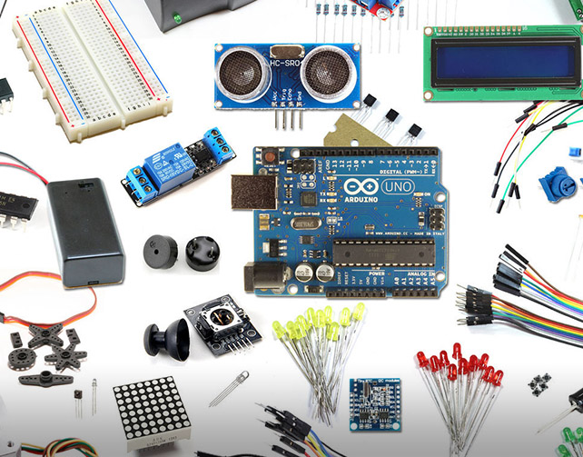
Set up the hardware connections with the Arduino and the servo motors. The continuous rotation servo motors are those types of servo motors that cannot be controlled or set at a particular angle, unlike normal servos. Servos have three wires coming from them: Red=Power, Black=Ground, White/Yellow=PWM/PPM Signal. The left servo motor (white/yellow wire) is hooked up to Arduino digital pin 9 and the right servo motor (white/yellow wire) to Arduino digital pin 10. The black wires of both the motors are connected to Arduino GND and the red wires to the positive terminal of the battery holder.
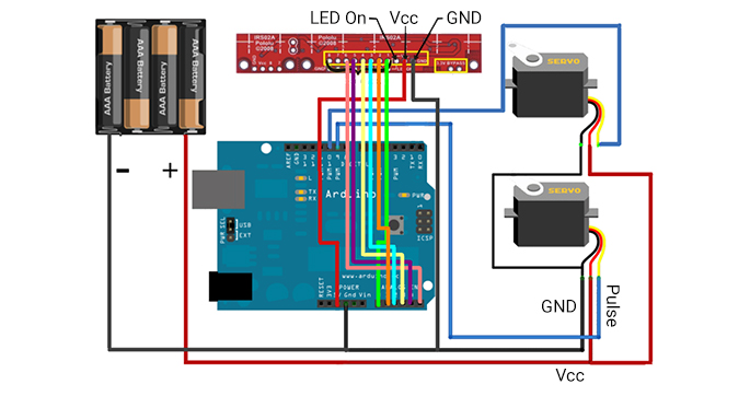
Pololu QTR-8A Reflectance Array Sensor
If you are using the Pololu sensor, and you don't need all eight IR detectors. You can remove two of them by cutting at the indicated perforation line on the board. The code we are using is only for six of them. Then solder some header pins to the board for VCC, GND, and signals 1,2,3,4,5,6. Connect the VCC and GND of this sensor to the Arduino's VCC and GND. The signals 1,2,..6 are connected to the Arduino's analog input pins A0, A1, A2, ...A5.
Using the Custom Fabricated Sensor Array
If you are using the custom fabricated sensor array, then short the anode terminals of all the IR LEDs together and connect to the Arduino VCC through a 220Ohm resistor. Next, short the cathode terminals together and connect to Arduino GND. Now, connect a 10K resistor to the cathode of each of the IR photodiodes. Short the free ends of all the 10K resistors together and connect it to Arduino Gnd. Now, short the anode terminals of the IR photodiodes together and connect it to Arduino VCC. Last, connect a wire to the cathode of each of the IR photodiodes (between the cathode and the 10K resistor). Connect each of the wires in sequence to Arduino's analog input pins A0, A1,..A5.